 It
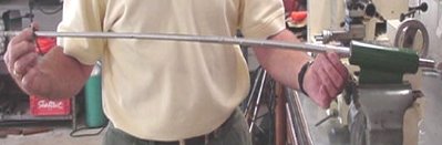
is not necessary for the bearings to be equally spaced over the shaft.
Many of the commercial feel-finders have two bearings only 6"-10"
apart, for the butt of the shaft to be inserted. This allows the device to be
packaged as two bearings in a tube. The JB spine finder at the right is
a prime example of this very common construction.. It
is not necessary for the bearings to be equally spaced over the shaft.
Many of the commercial feel-finders have two bearings only 6"-10"
apart, for the butt of the shaft to be inserted. This allows the device to be
packaged as two bearings in a tube. The JB spine finder at the right is
a prime example of this very common construction.. |
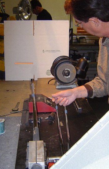
 When
the two bearings for the shaft butt are packaged together, the third
bearing is often hand-held. Or it may be omitted altogether, leaving
the fingers acting as the tip bearing. Here the JB finder is
demonstrated by Jerry Ballard himself. When
the two bearings for the shaft butt are packaged together, the third
bearing is often hand-held. Or it may be omitted altogether, leaving
the fingers acting as the tip bearing. Here the JB finder is
demonstrated by Jerry Ballard himself. |
 There
are quite a few instruments designed primarily as deflection analyzers,
but which also advertise themselves as spine finders. One might be led
by their advertising to believe that they are not just feel finders,
because they measure the load on the shaft due to a deflection
--
the definition of shaft stiffness. There
are quite a few instruments designed primarily as deflection analyzers,
but which also advertise themselves as spine finders. One might be led
by their advertising to believe that they are not just feel finders,
because they measure the load on the shaft due to a deflection
--
the definition of shaft stiffness.But one look at their configuration shows them to be identical to the "principles" diagram above. And, if we tested the same steel shaft (with no spine and 3mm residual bend), the instrument would tell us -- very precisely, in fact -- that it is a Type 1 shaft with a 30% spine. So, no matter how precise the output reading is, you still can't tell how much of the indicated load is the spine and how much is an artifact of residual bend. The GolfMechanix Auditor (shown in the photo) is a good example of this type of instrument. Others that fit the description are the Flexmaster, the NeuFinder 2, and the MCC Multi-Match. I have heard such gadgets defended as being more precise than feel finders. And they are. But -- much more important -- they are not a bit more accurate than feel finders, which is not very accurate at all. (If you are confused about the difference between precision and accuracy, see my article on the subject.) |
 |
 You can tell which FLO plane is the spine and which the NBP by using a frequency meter. The higher of the two frequencies is the spine. (In a pinch, a feel-finder may be useful to tell which FLO plane is which.) |
 And here is an actual video
of a shaft in non-FLO motion. (Click on the snapshot to watch the
video.) It starts in a good up-down motion, but "ovals" out of it in a
few vibrations. After ovaling a while, it briefly flattens again in a
different direction from the original. But it ovals again before
returning to the original up-down motion. This shaft has a very
prominent spine; most will take longer to go out of flat.
And here is an actual video
of a shaft in non-FLO motion. (Click on the snapshot to watch the
video.) It starts in a good up-down motion, but "ovals" out of it in a
few vibrations. After ovaling a while, it briefly flattens again in a
different direction from the original. But it ovals again before
returning to the original up-down motion. This shaft has a very
prominent spine; most will take longer to go out of flat.TECH NOTE 29: In the spine alignment process we try to determine the two planes in a shaft that produce flat line oscillation, i.e. no wobble. This is very often done with a tip weight rather than the actual clubhead. The questions arises," will the FLO change when I install the head because its center of gravity is offset from the centerline of the shaft?" Golfsmith claims it will not change. I was curious. If a change in FLO does occur is it due to the change in cg or because it's hard to twang the club straight up and down when your finger is twanging somewhere out on the clubhead rather than on the centerline of the shaft?
You may have heard of PURED shafts. They are shafts whose FLO has been found using a proprietary machine from SST PURE (Dick Weiss' company). The machine uses a computer-controlled process to home in on the FLO plane by examining the wobble quantitatively and deducing the FLO plane from the details of the wobble. To do that, you need a mathematical model of the wobble. Fortunately, the vibration of a clamped shaft with a spine is remarkably simple as mathematical models go. You can see the model and a derivation of it in my article on FLO.
Let's finish the section on FLO by repeating: One does not find FLO because FLO is important in characterizing the motion of the shaft during the swing. One finds FLO because FLO is a reliable way to find the stiffest and softest flex directions of a shaft. The NeuFinder 4
(a 2004 upgrade from the NeuFinder 2) was designed with differential
deflection in mind. A load reading is taken by measuring the increase
in load as the toggle lever moves from the pre-load stop to fully
deflected. The distance D is set by the height of the pre-load stop,
which is the most important part of the calibration of the instrument. The NeuFinder 4
(a 2004 upgrade from the NeuFinder 2) was designed with differential
deflection in mind. A load reading is taken by measuring the increase
in load as the toggle lever moves from the pre-load stop to fully
deflected. The distance D is set by the height of the pre-load stop,
which is the most important part of the calibration of the instrument.Important point: the shaft is resting in a V-block instead of bearings at its middle support. This provides enough friction so the shaft will not roll to the direction of minimum resistance. As noted above, the shaft must stay put in each position for differential deflection to work. The NeuFinder 4, as all the instruments that do differential deflection, has a "Tare/zero" button on its digital readout. So you don't have to do arithmetic to use it. Pre-load the shaft, zero the readout, then deflect the shaft. The readout now shows the differential deflection -- no subtraction needed. |
The Flexmaster can be used for differential deflection spine finding, with a couple of caveats:
|
| John Kaufman home-built his own differential detection jig, which he called an Inverted Flex Board.
It's pretty simple. You could build one yourself if you have a digital
scale with a tare/zero button. He makes the deflection distance D
repeatable by adding a spacer (the same spacer every time) under the
V-block that supports the shaft. Very clever. |
Which brings us to the question, "What measurements do you take, and how do you interpret them to find spine and NBP?" Here
is a sample set of measurements. I have taken an AJ Tech shaft, and
measured it at 10* increments. I selected this shaft to start because
AJ Tech is known for very large spines, and this shaft is no exception.
It should be easy to see and find the spine and NBP. Here
is a sample set of measurements. I have taken an AJ Tech shaft, and
measured it at 10* increments. I selected this shaft to start because
AJ Tech is known for very large spines, and this shaft is no exception.
It should be easy to see and find the spine and NBP.Sure enough, the graph of load vs angle is roughly a sine wave. The peaks are at 120ş and 300ş, and the valleys at 30ş and 210ş. We know by definition that the spine is the direction of maximum stiffness (the peaks) and the NBP is the direction of minimum stiffness (the valleys). This certainly confirms the rules for the arrangement of spines that we learned from engineering mechanics. The graph is not a smooth sine wave because of imprecision in the measurement. The digital readout of the NeuFinder 4 has a resolution of 0.01, and a precision (repeatability) of perhaps a bit more than that (0.01 to 0.02). On top of that, it is very hard to align the shaft to a precision of better than 10ş. So the sine wave has "jaggies" because of the slightly-off measurements. This is not a problem with a high-spine shaft like the AJ Tech, but... |
 Here are a few more shafts. (I have left the AJ Tech there for comparison.) Here are a few more shafts. (I have left the AJ Tech there for comparison.)
|