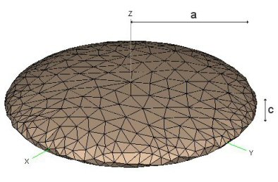
Figure 2-1
(From the FEKO web site)
It is possible to compute the Ih and Iv for an oblate spheroid. Assuming the spheroid is not solid, but rather a shell of uniform thickness, the equations are:
Ih = 2/3 m a2Using a typical driver mass of 200g, the computed moments of inertia are:
Iv = 1/3 m (a2 + c2)
Ih = 4550 gram-cm2
Iv = 2950 gram-cm2
But, before I injure myself patting myself on the back, I better note that it is well below the norm for the values in the Golfsmith catalog. Moreover, it does not show much promise of getting near the legal limit set by the Rules. Here is my explanation why the formula should give realistic but low-end values of MOI.
Until quite recently, 460cc heads had significantly higher moments of inertia than previous, smaller heads. So designers were happy to sell them as improvements. A few years ago, there was competitive parity at that point -- 4200 to 4500 g-cm2 -- so designers looked for new ways to increase MOI. They did it by abandoning the uniform thin shell (the assumption in our oblate spheroid model), and lightening some parts of the shell so they could add weight elsewhere and increase the MOI. (In the business, this is called "discretionary weight": weight that is not necessary for structural integrity, so it can be moved to affect things like MOI or CG position.)
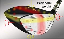
Figure 2-2 Using discretionary weight produces a higher Ih than our model accounts for. But what does this do to Iv? Figure 2-2 shows:
- Where you want to add weight to increase Ih (the airbrushed yellow band around the periphery),
- And where weight will increase Iv (the red band around the top and bottom).
| What designers do to increase Ih |
What that does to Iv |
| Move weight to the rear of the clubhead. | Same increase in moment of inertia. |
| Increase the depth of the clubhead. | Same increase in moment of inertia. |
| Move weight to heel and toe. | No effect on Iv. |
| Remove weight from crown to obtain discretionary weight for elsewhere. | Reduces Iv. |
| Face and sole are hard to take weight from; weight is needed there for structural reasons. And adding weight there does little for Ih, so that is not a candidate. | No effect on Iv. |
| Make the head wider (requiring it to be flatter to stay at 460cc). | Reduces Iv. |
There are two distinctly different possibilities of the best way to estimate Iv. Without actually measuring heads -- which I am not equipped to do, and such measurements are not widely published -- it is hard to tell which of the two views of Iv is closer to fact. FWIW, here they are:
- The changes in the above table that increase Ih tend to be somewhere between neutral and a reduction in Iv. So, while the oblate spheroid model shows Iv to be about 2/3 of Ih, it is probably less than that for driver heads with Ih of 5000 g-cm2 or more. I am just guessing, but I would use a value of about half Ih for a head that pushes the USGA limit of 5900 g-cm2. Note that half of 5900 is 2950 -- exactly the same Iv that we computed for the oblate spheroid. Coincidence or not? I don't know. In any event, it looks like somewhere around 3000 g-cm2 is a reasonable value of Iv to use for our sample calculations.
- Let us remember that the ratio of C to Ih is remarkably constant over a lot of drivers with a variety of moments of inertia. That suggests that the prevalent tool used by designers to boost MOI involves moving weight rearward. That is one of the few items in the table above that increases Iv as it increases Ih. So perhaps the ratio of C to Iv is similarly constant. If so, the ratio runs at about 3/2 that of C to Ih, making vertical spin computable as 1.5*16.4Vby.
s = 25 Vb y (Equation 3a)Once again, let's run some real numbers as a sanity test, and compare them with any data that might be around. We will start with our old standby of 150mph ball speed and 11º of loft. We will assume a face roll of 12" radius, same as the bulge. A center-face hit (y=0) will give a distance of 241 yards, as we expected.
Let's move up on the face as high as we dare without losing COR. I'd estimate that to be about 5/8", based on measuring the same drivers I did before. Equation 3a becomes
s = 25 Vb y = 25 * 150 * .625 = 2344rpmThat's a lot of spin! And it comes straight off the backspin applied by loft. (Assuming, of course, that the clubhead can rotate freely -- a question we address at the end of this article. But for now let's assume that clubhead rotation is unrestricted.)
How does this square with other investigators of vertical gear effect? Almost everyone I know of has reported much smaller numbers, seldom above 500rpm. Almost everyone. But Dana Upshaw has published data suggesting numbers in this general range. His launch monitor numbers -- 3300rpm difference in spin for a 1.5" difference in height at a ball speed of about 140mph -- are about 63% of the equation's estimate. Not the same, but in the ballpark.
Spin optimization
Since the contribution of vertical gear effect spin is obviously substantial, we need to ask what it does to the trajectory and the distance. We know that many (perhaps all) golfers will get more total distance with a higher launch angle and less spin than they'd get from a normal center hit on a driver of the "best" loft for their clubhead speed. But that's "and", not "or"; if you increase launch angle at the expense of higher spin, or vice versa, you will lose distance, not gain it. And there are only two ways of independently adjusting launch angle and spin to accomlish this:- Increase the angle of attack! This increases launch angle without changing the spin.
- Vertical gear effect! This decreses the spin with minimal change of launch angle. (And that minimal change is in the right direction.)
What happens if we keep the launch angle, but cut the backspin by the amount of gear effect? 3987rpm backspin minus 2344rpm gear effect is 1643rpm net backspin? Whoops! We just lost even more distance. Now we're only 230 yards, down 11 yards from the original 241. We obviously needed some of that spin. But not all of it. A quick optimization with TrajectoWare Drive says a gear effect spin of about 1000rpm would be optimal for that 12° launch. It would cut the spin to just under 3000rpm, add a few yards to the carry, and keep the angle of descent at a reasonable 37°.
There must be some reason we are told to hit high on the face. A few possibilities:
- We went too far when we went to 5/8".
- The shaft restricts the rotation of the head, so not as much spin is produced. Less than half of that gear effect spin would be just right.
- That is where the engineers designed the face for maximum COR. Not likely! It is harder to do than at the center of the clubface, and the engineers' real goal is to make the COR the maximum allowed over the whole clubface. Let's dismiss this out of hand.
| Height of impact |
Loft
at point of impact |
Backspin due to loft |
Topspin due to gear effect |
Net backspin |
Distance (yards) |
Angle of descent |
| Center | 11° | 3135 rpm | 0 | 3135 rpm | 240.5 | 34° |
| 0.2" above | 12° | 3416 rpm | 750 rpm | 2666 rpm | 239.3 | 32° |
| 0.4" above | 12.9° | 3668 rpm | 1500 rpm | 2168 rpm | 235.3 | 30° |
| 0.6" above | 13.9° | 3947 rpm | 2250 rpm | 1697 rpm | 230.0 | 28° |
Conclusions:
- A lot of topspin is generated (actually, a lot of backspin is eliminated). It is too much gear effect to increase the carry for the increased launch angle. The good news is the reduced angle of descent, which will increase the roll after landing.
- We need to see what is behind "door b" -- the restriction of clubhead rotation by the stiffness of the shaft tip. We'll look at that later.
It has been said that god is in the details. There is one detail we have been ignoring.
Figure 2-3
So far, we have treated the force as being in the direction of the clubhead's movement, as shown in the left image of Figure 2-3. Let's remember that the force is Newton's "equal and opposite reaction" to the departure of the golf ball. A more accurate picture would have the force exactly opposite the departure direction of the ball -- the launch angle -- as shown in the right image of Figure 2-3. This will make a very small difference in C and a much larger difference in y, both in such a direction as to reduce the gear effect. Specifically:
C = D cos aWhere
y = H - D sin a
- a = launch angle
- D = depth of CG from the center of the face (what we had been calling C until now.)
- H = height of impact above the center of the face (what we had been calling y until now.)
| Height of impact |
Loft
at point of impact |
Launch angle |
Actual y |
Backspin due to loft |
Topspin due to gear effect |
Net backspin |
Distance (yards) |
Angle of descent |
| Center | 11° | 9.7° | -0.22" | 3135 rpm | -825 rpm | 3960 rpm | 237.2 | 41° |
| 0.2" above | 12° | 10.5° | -0.04" | 3416 rpm | -150 rpm | 3566 rpm | 241.6 | 39° |
| 0.4" above | 12.9° | 11.2° | 0.15" | 3668 rpm | 563 rpm | 3105 rpm | 244.5 | 37° |
| 0.6" above | 13.9° | 12° | 0.33" | 3947 rpm | 1238 rpm | 2709 rpm | 245.7 | 35° |
| 0.8" above | 14.8° | 12.7° | 0.51" | 4198 rpm | 1913 rpm | 2285 rpm | 244.9 | 34° |
This is more like it! This is what we should have expected. We can wring quite a few extra yards of carry out of a strike 1/2" to 3/4" above the center of the clubface -- and get a bonus of more roll after landing (a consequence of the lower angle of descent).
A few points to carry away from this table:
- A center strike will create vertical gear effect to increase the backspin. That is because the force passes below the CG and rotates the face downward.
- In fact, you have to strike almost 1/4" above center face just to be gear-effect neutral -- no spin due to gear effect. You need that just to get the "nominal" distance out of the driver.
- The topspin due to vertical gear effect looks much more reasonable here. It is still higher than most estimates, but not by nearly as much as before. But...
- If we looked at the consequence of a low hit, we see oodles of gear effect backspin. If we go between 3/4" high and 3/4" low (a total of 1.5") we still see the same spin difference of 5600rpm. But it is biased more towards backspin, since the spin-neutral point is almost 1/4" above the center of the face.
The conclusion from this is that vertical gear effect is a very good reason to try to hit your driver high on the clubface.
Before we leave the subject, I'd like to point out that the real gains will probably be smaller than those in the table. The table was based on a ball speed of 150mph for all the rows. But there are small losses of ball speed as impact moves up the face, due to:
- As we can see in Figure 1-3, the sideways velocity of the face (which creates the gear effect) is accompanied by a backwards velocity. This is essentially a loss of clubhead speed. For a strike 0.6" above center, this is a loss of 1.5%. (But that is not a loss compared with a center strike, which also has a gear effect loss of about 1%. The lossless strike occurs where y=0, about 0.22" above center.)
- There may be some falloff of COR away from the center of the face. How much? That depends on the clubhead designer, and how well it was designed to keep the maximum COR over as much of the face as possible.