All about Gear Effect - 4
Dave
Tutelman --
February 20, 2009
Does shaft tip
stiffness limit vertical gear effect?
It had never really occurred to me to investigate this. After all, my
previous studies were pretty clear that:
Why would I expect this answer to come out differently?
Then, over the last couple of months, three different people pointed me
to a 3-year-old post by Dana
Upshaw on Tom
Wishon's forum. Dana wrote:
Posted - Sep
20 2005 : 8:05:20 PM
|
I'm going to make a
counter arguement and state that vertical gear effect is a significant
factor in reducing spin. My experimentation with large, deep face,
discretionary weighted heads and shafts of varying tip strengths have
shown me that the larger the head, the more the weight is low and back,
and the softer the shaft tip (to reduce resistance to the clubhead
"turning under" with impact high on the clubface) the more the spin can
be reduced IF the ball is impacted with an ascending blow and contacted
high on the face. I've personally recorded back spin rates as low as
70rpm at 170mph ball velocity (seventy...not 700 with a typo) with such
a setup, but I never could get the spin that low with the same head,
same swing, and same impact with a stiffer tip shaft.
One of
my clients is Brian Nash. He's a four-year member of the Pinnacle Long
Drive Team, a frequent Re/Max finalist, and makes his living traveling
the world conducting long-drive exhibits and corporate outings. A
couple of months ago he walks in with some new 8* Cobra heads and says
he's got to get his launch angle up with the new shorter shaft lengths
now being used (50" standup method which is about 48.5" USGA method). I
put the club together and he called me the next day from the course
saying he was hitting it 360 carry and the ball would roll to about
361. Too much spin from too much loft. I assembled another club using
one of his 6* Cobra heads and a VERY soft tip shaft and had him come
pick it up. Same hole on the course, same conditions, same launch
angle, same carry, but rolls to 390! He's experienced enough to know
when the ball is spinning and when it's not and his excitement about
"just about no spin at all" was evident. He hits it with an ascending
AoA and catches the upper third of the face all the time. And yes, he
makes a great scramble partner!
Now let's go to the other
extreme. I fit a distance-challenged lady with a 72mph driver speed.
She had several traditional weighted drivers and all produced just
about the same launch conditions. I showed here how to tee it high and
let it fly with an ascending AoA and they still all acted about the
same. I then let her hit my driver that matches the above description
and her backspin dropped down to 800-900 rpms. I made her one just like
mine and in two weeks her handicap dropped from 6 to 2 as she picked up
30 YARDS of roll and could now reach par 4s and 5s that she could only
get close to before!
All that said, none of it works without an
ascending AOA and contacting the upper center of the face to induce the
vertical gear effect. A descending AOA or a thin hit will both spin the
ball a lot. Both at the same time will result in spin rates up to 6000
rpms and produce a no-roll balloon ball.
It's never all "arrow",
but capitalizing on extremes of CoG location and shaft tip stiffness
will certainly aid the "indian" when swung correctly.
My nickle's worth....
|
I sure can't come up with a better explanation of the results than:
- Vertical gear effect can have a significant effect on
driver backspin. (But we knew that a few pages ago).
- The shaft can have a significant effect on vertical gear
effect.
Let's add to this "new information" a few more posts from various
forums:
- Tom
Wishon has posted that vertical gear effect is good for no
more than 300-500rpm.
- Dana
Upshaw has posted
launch monitor data with a difference of 3300rpm between a top and a
bottom hit (almost a 2" vertical difference) at less than 150mph ball
speed.
Wishon and Upshaw both have tons of experience and good
insight into what they are doing. So why the huge difference? And whom
to believe? Well, we know from the analysis
earlier in the article
that numbers like Upshaw's -- and even higher -- are mathematically
possible. If there is something substantially different between their
experiments that is causing the discrepancies, it has to be something
other than the usual suspects, like moment of inertia, ball speed,
clubhead design, or the size or type of the miss. Even added together
they
don't account for as much as half the difference. Moreover, equation 3a
-- our fundamental model of vertical gear effect -- held up very well
against real
measured data.
So let's investigate the explanation suggested by Dana's first
post: the tip stiffness of the shaft.
The approach will be similar to what we did for shaft torque and
horizontal gear effect. But it is harder this time. The steps:
- Find the size of the vertical-plane torque applied to the
head by the ball.
- Find the amount of vertical rotation during impact,
assuming no resistance provided by the shaft.
- Find the amount of torque resistance the shaft could
provide, given that amount of rotation. This is hard. There is no shaft
specification comparable to the torque rating, to help us with this.
Much of our investigation will necessarily be a search for this number.
- See whether the
shaft resistance induced by the rotation is a significant fraction of
the
torque we found in step #1 above. If not, then shaft stiffness cannot
limit vertical gear effect.
1. Find the vertical-plane torque applied to the
head
by the ball.
This is no different from what we did before, except that we are now in
a vertical plane. So:
Τavg
= .771 yVb
The units are foot-pounds for torque, inches for y,
and miles per hour for Vb.
2. Find the vertical rotation during impact, with no
shaft resistance.
By the same reasoning:
The units are degrees for rotation, inches for y,
miles per hour for Vb,
and gram-centimeters-squared for Iv.
This time, we'd like to plot how we got to this total rotation.
Assuming a constant moment (not accurate, but it will give us a
reasonable approximation), the degrees of rotation during impact is a
square-law curve based on the rotational analog of the well-known
linear motion equation:
x = ½at2
We already know x (the
rotation)
at time t=.5msec; we can plug that in for x and solve
for a:
| rotation =
74.2 Vb |
y
Iv | = ½a(0.5)2 |
where t is in milliseconds. If we plug this back into ½at2, we get:
| rotation(t) =
297 |
Vb
Iv |
y t2 |
0
≤ t
≤ 0.5 msec
|
We will use this later in step #4.
3. Find
the amount of resistance to that rotation the shaft could provide.
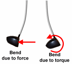
Figure 4-1Now
we get to the hard part. One of
the things that makes it hard is that the clubhead can apply two
contradictory loads at the tip of the shaft. Consider the case where
the impact is high on the face. That generates a load (shown in Figure
4-1) which is a
composite of:
- A force against the face, which tends to bend the tip
of the shaft backward.
- A torque to point the clubhead face-up, which tends
to bend the tip of the shaft forward.
How
does the shaft resolve these conflicting demands? First let us examine
the static case. We will do a classical analysis of a cantilever beam
with both a point load and a separate moment (torque) at the tip. If
you are interested in how we do the analysis, it is in the appendix.
Below, we continue with the results of the analysis.
|

Figure 4-2For a shaft of length L
and a uniform stiffness EI, we
can find the shape of the deflection -- and, from that, the tip angle.
| Deflection at x = |
Vb
75.3
EI |
x2
( y + x/3 - L ) |
When this is differentiated to give the tip angle (and converted from
radians to degrees), we find
| Tip Angle = |
1.52 Vb
EI |
L(y - L/2) |
It is worth noting that the strength of the impact (given by ball speed
Vb)
and the stiffness of the shaft (EI)
determine the size of the bend
or the tip angle, but not the shape
of
the bend. They just scale the result.
Figure 4-2 is a picture plotted from the deflection equation: a
collection of
shaft bends as we vary how high the ball
strikes the face. We use the typical length of a commercial driver,
45". Observations:
- A center-face hit (the black shaft) just bends the
shaft backwards. This should be expected, because y=0
so the turning moment is zero. There is only a force pushing the head
backward.
- They height of the hit on the face does not seem to
matter much. The yellow and purple shafts represent hits a full inch
above and below the center of the face, almost off the face and almost
certainly well away from a point of good COR. Even so, this fairly
extreme bending moment has very little effect on the shape of the bend.
There is a little less backwards-downwards tilt for the high hit, but
the difference is minimal.
- Here is an explanation for the very small difference.
We know the moment exerted by the force of the ball on the clubhead
(call it F) is Fy.
But the bending moment exerted by F
on the length of the shaft is F(L-x)
at point x on the shaft. So, for
most of the length of the shaft, the bending moment due to the F
bending the whole shaft back is much more than the Fy
moment. The result: the turning moment has a lot less effect than the
backwards force in creating tip deflection.
|


Figure 4-3But is that really how a shaft
behaves?
Well... No!
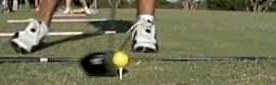
I asked Russ
Ryden to capture impact and post-impact shaft behavior with
his high-speed video camera. He loves this sort of stuff, and made a
real project of it. We are still analyzing all the data, but here are a
couple of videos that came out of Russ' efforts. They are slowed down
even beyond the 1200 frames per second at which they were shot, so you
can see them frame by frame. The frame interval is about 0.8
millisecond,
or roughly twice the duration of impact.
The first video shows behavior at impact for a high-face hit with a
shaft of medium tip stiffness. We see a lot more forward bend
(moment-induced, not force-induced) than we would expect. But it occurs
only near the tip, say within a foot of the clubhead. Moreover, it
appears in the frame or two after impact (that is, the first
millisecond or so after impact), and quickly vanishes. What is going on
here?
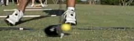
The explanation becomes more clear when we look at the second video.
There are two important differences: (i) the shaft is much more
flexible, and (ii) it is close to a center hit, so all the bend is
backwards. What we see is a wave of backwards bend starting near the
clubhead and propagating up the shaft. The wave traverses the first two
feet of the shaft in about four frames, or 3.3 milliseconds. So the
speed of the wave up the shaft is about 0.6 foot/msec.
Thus our first static analysis that assumes the whole shaft is involved
during
impact is not a valid view, and not very useful for analysis purposes.
If the wave travels at 0.6 foot/msec, only the bottom 4" of shaft tip
can
be involved in resisting clubhead rotation during impact. (Yes, a lot
more of the shaft can be involved in all the clubhead rotation during
the follow-through. But that does not influence ball flight; only head
motion during impact can do that.)
|
The details of impact are very difficult to analyze without dynamic FEA
software. But we can get a ballpark estimate of the ability of the
shaft to resist rotation during impact. Let's look again at the static
deflection formula, but this time limit the length to just the portion
of the shaft that might be involved before the ball has left the
clubface. That would be about 4" of shaft. Let's look at the shaft bend
as the wave grows from 0" to 4" during impact. Here are shaft
deflection curves for lengths of 1", 2", and 3".
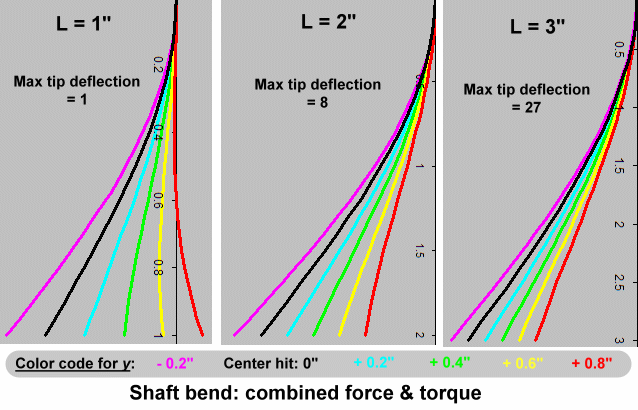
Figure 4-4
Bear in mind that the graphs have been scaled so that detail will
show. The 2" graph is really 8 times as wide as the 1" graph, and the
3" graph is 27 times as wide. That is because deflection grows rapidly
as beam length increases; it is a cube-law relation.
The major conclusion I draw from Figure 4-4 is that, although the shaft
might allow some upwards rotation early in the strike, the bend is all
backwards for most of the duration of impact. By the time the ball
releases from the clubface all the rotation is downward, and the
differences in rotation due to height of impact are quite small.
|

t - 0.8msec |
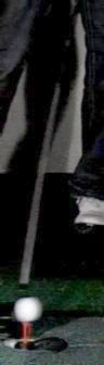
Impact |
t + 0.8msec |
t + 1.6msec |
Figure 4-5
It's time to ask ourselves again, is
that really how a shaft behaves?
We're closer now, but the answer is still no. Let's look again
at Russ
Ryden's
videos. In Figure 4-5, we have taken snapshots of the first video --
the
high-face hit -- in the vicinity of impact. If our analytical model
were
correct, then we might see a bit of sharp forward bend in the impact
snapshot -- and only if it occurred early during the 0.5msec of impact.
By the end of impact, the wave should have traveled 4" up the shaft and
all the
bend is backward.
But what we actually see is a significant forward bend after the ball
leaves
the clubface. In fact, it is forward bend propagating up the shaft as
the flex wave.
This is not at all what Figure 4-4 says will happen. That set of
graphs, computed from the equations, predicts that any forward bend
will disappear as the wave (the effective beam length) moves up the
shaft during impact. By the time the ball releases from the clubface,
all the bend is backward. But the snapshots in Figure 4-5 have a
forward bend well after release!
What is wrong with the analytical model, and how can we fix it? The
problem is that the model is still largely static. We have incorporated
the flex wave to dynamically limit the length of shaft involved during
impact. But we are still not accounting for the fact that some of the
force and moment (P and M)
are absorbed by the inertia of the clubhead and never get to the shaft
at all, or at least not during impact. So the shaft sees less backward
bend than P and less rotational
moment than M. And the reduction
may not be in equal proportion, because the mass (which resists P)
is not the same as the moment of inertia (which resists M).
The way to resolve this is to separate out the response into
independent fractions, as follows:
- ap is
the fraction of the force absorbed by shaft flex.
- 1-ap
is the fraction of the force absorbed by the clubhead's mass.
- am is
the fraction of the moment absorbed by shaft flex.
- 1-am
is the fraction of the moment absorbed by the clubhead's moment of
inertia.
When we do that, the equations for deflection and tip angle become:
| Deflection at x = |
Vb
75.3
EI |
x2
( amy
+ apx/3
- apL
) |
| Tip Angle = |
1.52 Vb
EI |
L(amy - apL/2) |
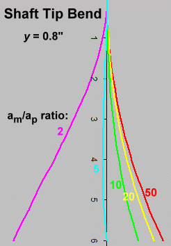
Figure 4-6
Again, let's plot the shape of the
shaft (the deflection curve). This time, we will try to come up with a
shape similar to the bend we see in Figure 4-5 at t+0.8msec,
immediately after impact. The photos show a very high-face hit and
about a 6" flex wave, so we will use y=0.8"
and L=6". We will vary am and
ap.
As it turns out, the shape depends on the ratio of am to
ap
and not their actual values (which determine only the magnitude of the
curve, not the shape).
There is a plot in Figure 4-6 for values of am/ap
from 2 to 50. It does not give a curve that looks remotely like Figure
4-5, the actual high-speed photo of the shaft tip, until am/ap
is at least 10. So there isn't anything there suggesting the force (ap)
being nearly as important as the moment (am) .
I first plotted
ratios from 0.1 to 10, but the values less than 5 didn't show forward
bend at all. In order to look anything like Figure 4-5, we need a
ratio of at least 10, and possibly more.
The conclusion we can draw from this is that, at least for Figure 4-5,
the clubhead's mass absorbs so much of P
that the shaft plays very little part in resisting the resulting
backward bend. So just about all the deflection is forward bend due to M.
So we should use the equations as if ap
is negligibly small compared to am.
That gives us a shaft that looks something
like Figure 4-5.
| Deflection at x = |
Vb
75.3
EI |
amx2y |
| Tip Angle = |
1.52 Vb
EI |
amLy |
The remaining prerequisite for relating clubhead rotation to
shaft reaction is the
EI of the shaft tip. I have
an EI
machine,
and measured the EI of several
known tip-stiff and tip-flexible shafts.
My machine allows a 6" tip reading, which should be good enough; few
shafts have much change of EI
over the last 6" of tip.
I measured several shafts, some known tip-soft and others tip-stiff.
For the units required by the equations, the lowest EI
measured was just over 5200 pound-inches2 and
the highest just under 14,000. (This corresponds to 14 and 40 N-m2
which is what the equations call for.) So tip stiffness covers
nearly a 3:1 range. It is the range we will use in the next part of the
analysis.
(Note: In practice, it would not be nearly as large as a 3:1 ratio. I
got it with a tip-flexible LL-flex shaft and a tip-stiff long driver's
XX-flex shaft. If you actually tried to fit a long drive competitor
with an LL-flex shaft, the tip stiffness would be the least of your
concerns. So, for a decent fit for a given golfer, the range of tip
stiffness will be a lot less than 3:1. But let us continue with that
ratio to keep things interesting.)
|
4. Compare shaft torque with impulse torque
Rather than compare torques directly, let's compute the amount of
clubhead rotation when constrained:
- Just by the moment of inertia.
- Just by the shaft.
Then we will compare the rotations from #1 and #2. If
the clubhead's inertia restricts rotation by an order of magnitude or
two more than the shaft does, then the shaft has no effect on vertical
gear effect, because the rotation never gets big enough during impact
to put much load on the shaft.
In step #2, we found that the rotation during impact, restricted only
by inertia, is given by:
| rotation =
297 |
Vb
Iv |
y t2 |
0
≤ t
≤ 0.5 |
In step #3, we found the rotation (tip angle) of the shaft when
subjected to the impulse moment of the ball is given by:
| Tip Angle = |
1.52 Vb
EI |
amLy |
The beam length L starts at
zero, and increases at a rate of 1.6 foot per millisecond,
corresponding
to the propagation of the flex wave.
Let's
plot the rotation of the clubhead restricted by inertia and by shaft,
and compare the plots. We will use the following values:
- Vb
= 150mph, though that will not matter. Vb cancels
out, because it is a proportional factor for both graphs.
- y = 0.8", though that
also cancels out for the same reason.
- Iv = 3100
g-cm2.
- am = 1.
We introduced am to
reflect the fact that clubhead inertia restricts the shaft's role to
some fraction. But the point of this plot is to see what happens if
shaft flex is unrestricted by inertia, so we set am to
1.
- EI = 14 - 40 N-m2.
We want to see how the effect of tip stiffness affects clubhead
rotation, so we will plot the extremes of tip stiffness.
Time
(milliseconds) |
Inertial rotation
(degrees) |
Beam length
of flex wave
(inches) |
Shaft Rotation
(degrees) |
| EI
= 14 |
EI
= 40 |
| 0 |
0 |
0 |
0 |
0 |
| 0.1 |
0.1 |
0.8 |
10.4 |
3.6 |
| 0.2 |
0.5 |
1.6 |
20.8 |
7.3 |
| 0.3 |
1.0 |
2.4 |
31.3 |
10.9 |
| 0.4 |
1.8 |
3.2 |
41.7 |
14.6 |
| 0.5 |
2.9 |
4.0 |
52.1 |
18.2 |
Now we compare how inertia limits the clubhead rotation (the yellow
column) with how shaft torque limits it (the green columns). At every
instant during impact, the shaft allows a lot more rotation than
inertia does.
- For the tip-flexible shaft (EI=14),
the shaft allows more than 18 times the rotation allowed by inertia, at
every moment during impact. We can safely say that the shaft imposes no
limit on the gear effect.
- For the tip-stiff shaft (EI=40),
the numbers are more equivocal. The shaft still allows much more
rotation than is allowed by inertia, but the factor is smaller. At its
maximum
influence just before release, the shaft allows 6 times the rotation
that inertia does. That suggests that the shaft is absorbing about 14%
of the moment, and inertia is absorbing 86%. Here is a table showing,
moment by moment during impact, the relative loads absorbed by the
shaft and the moment of inertia for a very tip-stiff shaft:
| Milliseconds |
Absorbed
by shaft |
Absorbed
by inertia |
| 0.1 |
3% |
97% |
| 0.2 |
6% |
94% |
| 0.3 |
8% |
92% |
| 0.4 |
11% |
89% |
| 0.5 |
14% |
86% |
Conclusion
My
conclusion from these numbers is that the tip stiffness of the shaft
might make as much as a 14% difference in the spin due to vertical gear
effect, but probably somewhat less and definitely not more than that.
I have mixed feelings about
this conclusion. I believe it, but I have less confidence in it than
the other results in this article. I went over the numbers many times
(and found a
few errors, mostly in unit conversions) before I was willing to post
the article. Arguments for and against the conclusion:
- Against
- It does not support Dana Upshaw's observation that tip stiffness can
make a huge difference in vertical gear effect. The conclusion suggests
a rather small difference. Explaining Dana's results would require a
tip-stiff shaft to provide most
of the rotation-limiting (not less than 14% as the
calculations say). That also means that even a tip-flexible shaft
should provide considerable limiting, since it will be at least 1/3 the
tip stiffness of the stiffest shaft (and probably more than that,
because the 3:1 ratio is not realistic).
- For
- The numbers in my analysis which are most suspect are the shaft
stiffness numbers. In order to get the sort of factor we would need to
reconcile Upshaw's results, we would need the shaft stiffness to be
much more limiting of the clubhead rotation than
the inertia. That would require a total clubhead rotation during impact
much less than inertia alone would allow, which is about 3º. But,
measuring the high-speed photos in Figure 4-5, it looks
like there is about a 3º head rotation during impact. The
rotation during
impact
roughly
corresponds to inertial rotation -- and thus suggests that the shaft
stiffness is not a major limiting factor.
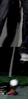
-
pre-
impact |
 |
post-
impact |
 |
+3.2
msec |
|
+6.4
msec |

|
+9.6
msec |
 |
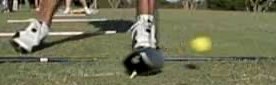
| Figure 4-7 |
For - Consider
another photo sequence from Russ Ryden's high-speed videos -- Figure
4-7. It doesn't show much shaft; instead, it follows the clubhead for
nearly ten milliseconds after impact. Note how dramatically the head
continues
to rotate more and more face-up long after the ball has released -- and
with it, any external moment trying to turn the head. What
can we make
of this?
We know from the analysis that the question -- does tip stiffness limit
vertical gear effect? -- depends on the balance between how much
bending moment is absorbed by inertia and how much by the shaft tip.
If, as Upshaw's anecdote suggests, the shaft's
tip stiffness had any significant contribution to limiting head
rotation during impact,
there certainly would not be much rotation after
impact. Once the ball leaves the clubhead, it is inertia, and only
inertia, that wants the
rotation to continue, and the shaft tip trying to stop and reverse the
rotation. If the shaft tip dominated inertia during impact, it
certainly will dominate it after impact when the external moment is
removed.
But what we in fact observe is that the shaft is
not taking charge. By
9.6msec
after release (about twenty times the duration of impact) the
clubhead's face-up rotation is probably ten times what it was at
release. This strongly suggests that the clubhead inertia Iv is
well
more than ten times as effective as shaft stiffness in limiting
clubhead rotation during impact.
So I publish these conclusions along with an invitation to show me my
mistake. It is entirely possible that I made one.
|

Last modified - Aug 1, 2020
|


