 If
you deflect the shaft and measure the spring constant (the stiffness),
then deflect it in exactly the opposite direction (that is, exactly
180º away), you will get the same spring constant. It is equally stiff
in both directions.
If
you deflect the shaft and measure the spring constant (the stiffness),
then deflect it in exactly the opposite direction (that is, exactly
180º away), you will get the same spring constant. It is equally stiff
in both directions.- If the cross-section of the beam is not perfectly
symmetrical, then the beam may have a strong plane (the
direction of highest spring constant) and a weak plane (the
direction of lowest spring constant). Clubmakers refer to the strong
plane as the spine
and the weak plane as the Natural Bending Position (NBP) -- or at least
they should if they are using the right measuring instruments.
Repeating that as a table, for clarity:
Strong plane Weak plane Direction of
highest spring constantDirection of
lowest spring constantSpine NBP
- The strong plane and the weak plane are 90º apart.
- Between the strong plane and the weak plane, the spring constant varies as an ellipse, as the diagram shows.
- If the shaft were perfectly symmetrical, then the ellipse would be a circle, and the spring constant would be the same in every direction. That would be a shaft with no spine.
Before we go any further, let's state some assumptions underlying the rest of the work:
- Whatever asymmetrical stiffness the shaft has, it is the same (including its orientation) for the length of the shaft. (It turns out that this isn't a major restriction, but it's hard to show that fact so I won't bother.)
- The shaft, when flexed either for "shaft art" or by a golf swing, remains a linear spring. Almost every spring material and spring design has some level of deflection where F=-Kx fails. We assume that this doesn't happen to our shaft in normal operation.
 One
final "basic". Let's look at how a shaft oscillates when there is
a spine -- how it gets from a planar up-down vibration to an
out-of-plane oval. Here is a video example, using a shaft with a really
substantial spine.
One
final "basic". Let's look at how a shaft oscillates when there is
a spine -- how it gets from a planar up-down vibration to an
out-of-plane oval. Here is a video example, using a shaft with a really
substantial spine.
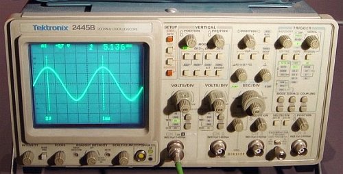
 This is useful when you want to
compare the frequencies of two waveforms. (Yeah, I know. Use a
frequency counter. That's how it would be done today. But frequency
counters were expensive and relatively rare in 1960,
while every electronics lab had oscilloscopes.
This is useful when you want to
compare the frequencies of two waveforms. (Yeah, I know. Use a
frequency counter. That's how it would be done today. But frequency
counters were expensive and relatively rare in 1960,
while every electronics lab had oscilloscopes. So,
if the frequencies are the same, you get some kind of ellipse. But what
happens if they are not the same? If they are far apart, then you get a
very interesting swirly pattern, that it takes some experience to
understand. But, for a clubmaker trying to understand FLO, the most
interesting case is when the horizontal and vertical waveforms have
almost the same frequency -- but not quite the same. When that happens,
it looks like a same-frequency ellipse, except that the phase keeps
changing because of the slight difference in frequency. The ellipse
keeps morphing on the screen, like the animated picture here.
So,
if the frequencies are the same, you get some kind of ellipse. But what
happens if they are not the same? If they are far apart, then you get a
very interesting swirly pattern, that it takes some experience to
understand. But, for a clubmaker trying to understand FLO, the most
interesting case is when the horizontal and vertical waveforms have
almost the same frequency -- but not quite the same. When that happens,
it looks like a same-frequency ellipse, except that the phase keeps
changing because of the slight difference in frequency. The ellipse
keeps morphing on the screen, like the animated picture here. I built a pendulum with two
frequencies, one frequency in one direction
and another frequency perpendicular to that direction. How can we do
that? We make the shape of the pendulum a "Y", as in the picture. The
three arms of the Y are string tied together. The pendulum is suspended
at two points (instead of the usual one), and there is a weighted bob
to provide the mass.
I built a pendulum with two
frequencies, one frequency in one direction
and another frequency perpendicular to that direction. How can we do
that? We make the shape of the pendulum a "Y", as in the picture. The
three arms of the Y are string tied together. The pendulum is suspended
at two points (instead of the usual one), and there is a weighted bob
to provide the mass.


 First let's specify the model of
the shaft. It consists of two springs, one on the weak axis (or NBP)
and the other on the strong axis (or spine). In the picture, the NBP is
vertical and the spine is horizontal.
First let's specify the model of
the shaft. It consists of two springs, one on the weak axis (or NBP)
and the other on the strong axis (or spine). In the picture, the NBP is
vertical and the spine is horizontal. Now what happens when we bend
the shaft? That depends on which direction we bend it.
Now what happens when we bend
the shaft? That depends on which direction we bend it. How about the angle of the
restoring force? It will be the resultant of two spring forces at right
angles to one another.
How about the angle of the
restoring force? It will be the resultant of two spring forces at right
angles to one another. So
the force (B) is always a little closer to the spine than the bend
itself (A). The difference angle (B-A), the angle between the bend and
the spring force that results, can be
computed without too much trouble:
So
the force (B) is always a little closer to the spine than the bend
itself (A). The difference angle (B-A), the angle between the bend and
the spring force that results, can be
computed without too much trouble: