
|
| Home ⇒ golf ⇒ biomech ⇒ Current Article |
Article
Contents
Application to the golf swing
| |||||||||||||||||||||||||||||||
Coordinate systemsAt the beginning of the book, where the concept of vectors was first introduced, it became clear that sometimes a proper choics of axes for the vectors would make the problem easier to formulate or to solve. Any particular choice of axes is called a "coordinate system". Before we talk about the coordinate systems commonly used in golf biomechanics, let's review some general principles for choosing a set of axes.
World coordinates - x,y,z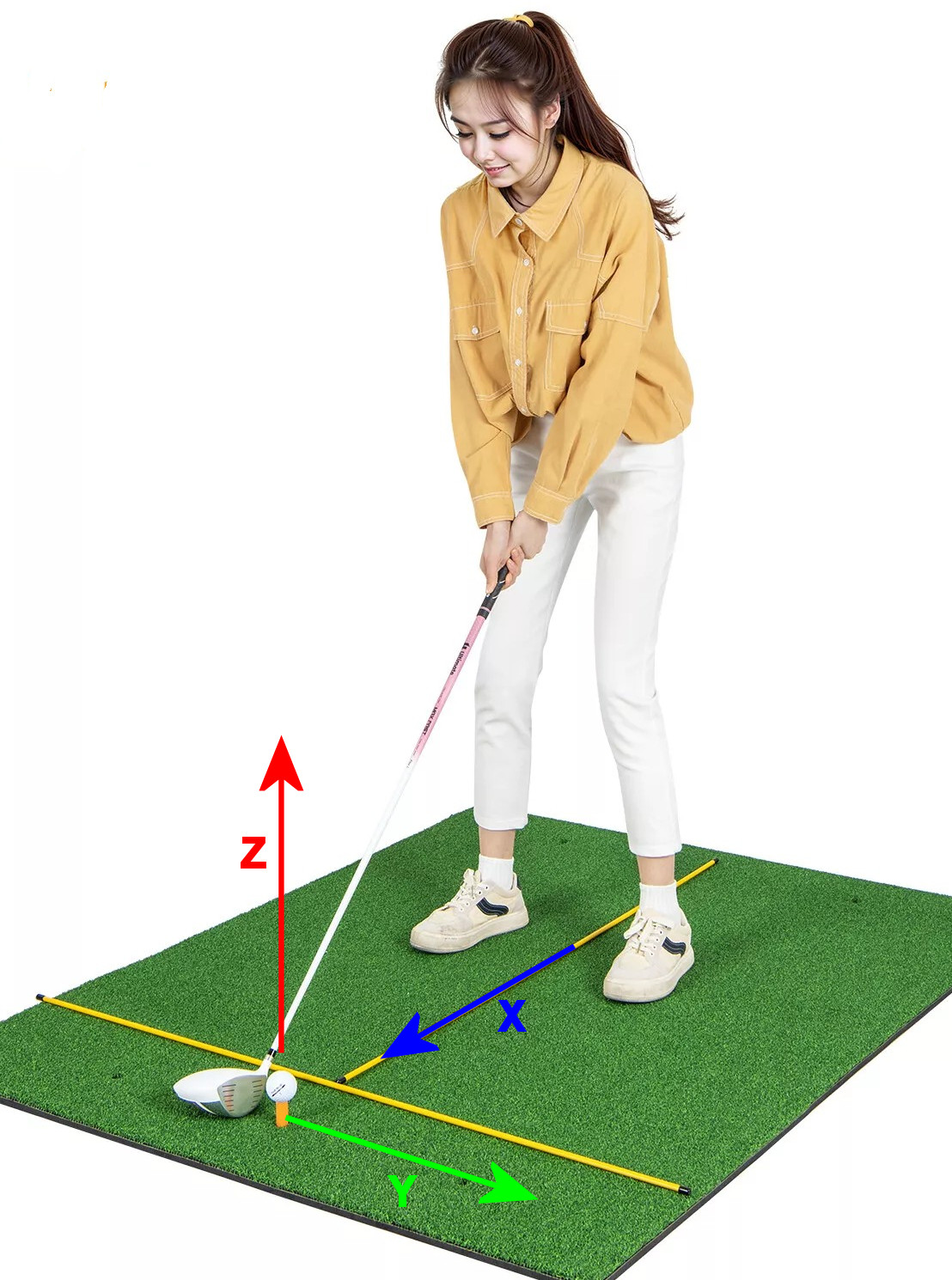 This
is the simplest coordinate system to visualize. It may not be the
system of choice for the computations, though it is for some problems.
But it is frequently what the results are converted to so the reader
can understand and appreciate them. This
is the simplest coordinate system to visualize. It may not be the
system of choice for the computations, though it is for some problems.
But it is frequently what the results are converted to so the reader
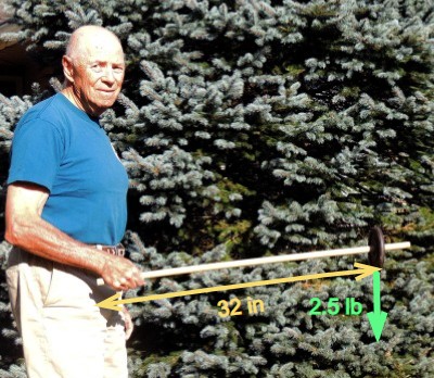
can understand and appreciate them.The diagram shows the world coordinates in the context of a golfer practicing with algnment sticks. The exercise is very common, and the sticks show the direction of the X and Y axes. The axes are all linear. They are:
|
||||||||||||||||
Swing plane coordinates - alpha,beta,gamma The
swing plane coordinate system is seldom if ever used to mathematically
model a golf swing. But it is exceptionally useful in understanding the
workings of the swing, so many analyses done in another coordinate
system are transformed into swing plane coordinates for the discussion
phase of the report. The
swing plane coordinate system is seldom if ever used to mathematically
model a golf swing. But it is exceptionally useful in understanding the
workings of the swing, so many analyses done in another coordinate
system are transformed into swing plane coordinates for the discussion
phase of the report.The three axes are all rotational, and their values would be measured in degrees, radians, revolutions, etc. They are:
Please do not ask detailed questions about this model yet. There are so many that would be difficult to answer with what we know so far. We will try to fill in any blanks as we go. |
||||||||||||||||
Right hand ruleAs soon as you start thinking constructively about the swing plane coordinates, a bunch of difficult questions arise. Probably the most difficult conceptually (not necessarily arithmetically) is the fact that we don't have a way to add torques that are in different planes -- at least not yet. We also need to include forces along with the torques, and we haven't covered how to resolve forces in a set of angular coordinates. Let's resolve those issues now.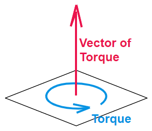 When
we draw a picture of a torque as a "circular arrow", it lies within a
plane. It is easy to visualize that way, but a circular arrow is not a vector. If we want to
treat torque as a vector, we need a different concept and a different
representation. And there is one. When
we draw a picture of a torque as a "circular arrow", it lies within a
plane. It is easy to visualize that way, but a circular arrow is not a vector. If we want to
treat torque as a vector, we need a different concept and a different
representation. And there is one.A torque is applied around an axis. When the torque provides angular acceleration, this axis is the axis of rotation. So let's represent torque as a vector along that axis, with a magnitude that is the size of the torque. It turns out that this representation works really well. In fact, we can add torques in 3D space by adding those vectors. The magnitude of the resultant vector is the size of the net torque. The sum-of-torques vector direction is the axis that the net torque would be applied to. |
||||||||||||||||
 The
remaining concern is the sign of the torque vector. Physicists the
world over have adopted a convention called "the right hand rule".
Here's how it works. The
remaining concern is the sign of the torque vector. Physicists the
world over have adopted a convention called "the right hand rule".
Here's how it works.You "grab" the axis of rotation or torque, with your right hand. Be sure it's the right hand; it comes out backwards if you use your left hand. The fingers have to wrap around the axis in the direction of the rotation or torque. If you do that, the thumb will point along the axis in the positive direction. BTW, it doesn't make any technical difference whether you use your right or left hand; it is merely a convention. As long as you are completely consistent, you will get an answer that will serve physics well. But you may have trouble explaining your work to someone using the right hand -- so everybody agrees to use the right hand. |
||||||||||||||||
Club coordinates - x,y,zIf you look back at the swing plane coordinate system, you will notice that the axes do not stay in the same place throughout the swing. This is easiest to see for the gamma axis. It is the centerline of the shaft. Of course, that moves as the shaft moves, changing direction quickly and drastically as the club swings. The beta axis changes as well, rotating around during the swing. If the swing were perfectly planar, then at least the alpha axis would be fixed. In fact, it is not a perfect plane, but it is close enough (especially, as we will see soon, the "functional swing plane") that we can get very useful answers from considering the alpha axis fixed. When
we think critically about the moving axes, we realize that they are
close to being fixed to the golf club itself, rather than fixed in
space. And indeed, an important coordinate system in many biomechanics
problems is a set of axes referred to the club itself. In this system: When
we think critically about the moving axes, we realize that they are
close to being fixed to the golf club itself, rather than fixed in
space. And indeed, an important coordinate system in many biomechanics
problems is a set of axes referred to the club itself. In this system:
Let's reinforce the workings of the right-hand rule by applying it to the club-referenced coordinates. Here is a table I originally put together for a previous study that used club coordinates.
|
||||||||||||||||
Other coordinate systemsThose are the three main coordinate systems you will encounter in discussions of golf biomechanics. But there are others you will see less frequently. Here are a few; let's just gloss over them to get the flavor of what is possible. The
first comes from a paper we mentioned above, the attempt by Choi
and
Park to distinguish the forces of the right and left hand. (That
turns
out to be a fairly difficult problem with conventional modeling, as we will see later.)
They took the idea of club-referenced coordinates and extended it to
each individual body part in their analysis. They have an [X,Y,Z]
coordinate system on each of: The
first comes from a paper we mentioned above, the attempt by Choi
and
Park to distinguish the forces of the right and left hand. (That
turns
out to be a fairly difficult problem with conventional modeling, as we will see later.)
They took the idea of club-referenced coordinates and extended it to
each individual body part in their analysis. They have an [X,Y,Z]
coordinate system on each of:
|
||||||||||||||||
 Here's
another system, though it isn't a full-fledged coordinate system. But
it looks like one because it orients everything in the body according
to three mutually perpendicular planes. It is the system the science of
anatomy uses to talk about the direction of anything the
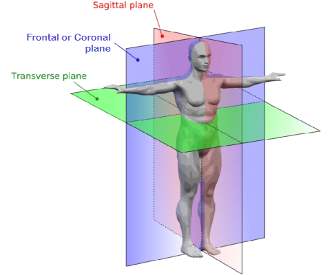
body is or does. Here's
another system, though it isn't a full-fledged coordinate system. But
it looks like one because it orients everything in the body according
to three mutually perpendicular planes. It is the system the science of
anatomy uses to talk about the direction of anything the
body is or does.I mention it because you will occasionally run across the terms "sagittal", "frontal" (AKA "coronal"), and "transverse" in golf biomechanics papers. It isn't usual, but it happens. This diagram should be all you need to understand what the author is saying. There are other, special-purpose coordinate systems that you might encounter. Now that you have seen a few, you should be able to figure them out when you run into them. |
||||||||||||||||
Functional swing planeOne of the coordinate systems above is referenced to the swing plane. But there are numerous studies that show the swing is not really planar; it doesn't restrict itself to a single plane. Some golfers have a more planar swing than others, but nobody is really close enough to model the entire swing with any accuracy using coordinates tied to some specification of the plane of the actual swing. Except for one such spec: the "functional swing plane". "Functional swing
plane" is a term originated by biomechanics professor Dr Young-Hoo Kwon
in a paper
co-authored with a number of his students (including Chris Como). It
refers to a portion of the late downswing and early follow-through
where the motion of the club is governed in large part by the momentum
of the club itself. The club-horizontal position in the downswing to
the club-horizontal position in the follow-through, shown in yellow, is
the functional swing plane. During this part of the swing, the angular
velocity of the club is such that it pulls outward very strongly. "Functional swing
plane" is a term originated by biomechanics professor Dr Young-Hoo Kwon
in a paper
co-authored with a number of his students (including Chris Como). It
refers to a portion of the late downswing and early follow-through
where the motion of the club is governed in large part by the momentum
of the club itself. The club-horizontal position in the downswing to
the club-horizontal position in the follow-through, shown in yellow, is
the functional swing plane. During this part of the swing, the angular
velocity of the club is such that it pulls outward very strongly.In fact, the functional swing plane is characterized by its stability. A more precise term is "stable equilibrium". That means that any attempt to move the club out of plane will itself create a force or torque to move it back into the functional swing plane. It is stable because any disturbing force is met automatically with a restoring force. Let's look at swing plane stability more closely. |
||||||||||||||||
The
stability comes from the centripetal force (a pull) the hands need to
exert on the grip in order to keep the club from flying off in a
straight line. The reaction to this force is an outward pull that the
clubhead exerts on the shaft tip. These forces are so large in a full
golf swing that out-of-plane forces trying to pull the club out of the
functional swing plane can't get it very far off plane. |
||||||||||||||||
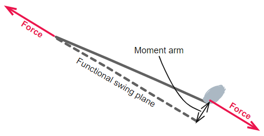 The
diagram shows the club angled away from the functional swing plane. The
beta angle is exaggerated so we can visualize it better; it is more
like 10° than 1°, but the calculations will proceed as if it is just 1°, The
diagram shows the club angled away from the functional swing plane. The
beta angle is exaggerated so we can visualize it better; it is more
like 10° than 1°, but the calculations will proceed as if it is just 1°,
|
||||||||||||||||
|
||||||||||||||||
Implications for 2-dimensional modelsI feel I have learned a lot about the swing from the double pendulum model. A detailed analysis based on the double pendulum was published by Theodore Jorgensen in the early 1990s, but it dates back at least to Alastair Cochran and John Stobbs in the 1960s. But any time I cite the double pendulum, someone is sure to criticize it as, "Oh, that's no good. It's 2D. You can only get worthwhile information from 3D models." While it is true that there is a lot that a 3D model might teach that you can't get from a 2D model, there is very little that the double pendulum teaches that is overturned by a 3D model.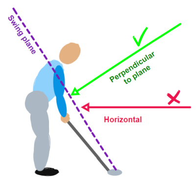 So
why this knee-jerk prejudice against 3D models, and an immediate
willingness to reject its teachings? The most obvious answer (obvious
to me, anyway) is the common -- and incorrect -- assumption that the 2D
plane in question is vertical, a face-on view of the swing. It can't
be, especially if there is an extremely stable functional swing plane
that is not
vertical. Everything going on with alpha torques and their
in-plane accelerations and motion is happening in the functional swing plane.
The only legitimate conclusion is that Cochran and Stobbs and Jorgensen
were talking about a pendulum in the swing plane. The valid view of
their 2D model is the green arrow in the image, not the red one. So
why this knee-jerk prejudice against 3D models, and an immediate
willingness to reject its teachings? The most obvious answer (obvious
to me, anyway) is the common -- and incorrect -- assumption that the 2D
plane in question is vertical, a face-on view of the swing. It can't
be, especially if there is an extremely stable functional swing plane
that is not
vertical. Everything going on with alpha torques and their
in-plane accelerations and motion is happening in the functional swing plane.
The only legitimate conclusion is that Cochran and Stobbs and Jorgensen
were talking about a pendulum in the swing plane. The valid view of
their 2D model is the green arrow in the image, not the red one.Here are some reasons that everybody assumes the the double-pendulum swing is vertical -- even though clear thinking indicates it should be on the plane of the actual swing.
|
||||||||||||||||
| The next question to ask about
2D models is what we lose by not
making it 3D. The first and most obvious thing we lose is any motion, force, or torque perpendicular to the swing plane. Those are completely lost; there is no way to even represent them in a 2D model, much less calculate or assess them. The most obvious such consideration is squaring of the clubface. That occurs at a substantial angle to the swing plane, and most of what causes it (rotation around the shaft axis) is completely normal to the swing plane. So we really have no way of talking about a square clubface in a 2D model that lives in the swing plane. But there are things that critics throw out that apply to the double pendulum model, but not to 2D models in general. Yes, the double pendulum is the first and simplest 2D model, but hardly the only one. For instance, I have heard the assertion that "parametric acceleration" can only be studied in 3D. Parametric acceleration is the angular acceleration of the golf club by pulling up and in on the handle during the last part of the downswing. It was introduced in a 2001 technical paper by K. Miura, and talked about in Book 1 without calling it parametric acceleration. (Let me urge you to review the latter reference. It will be essential to understanding how the golf swing is really powered.) 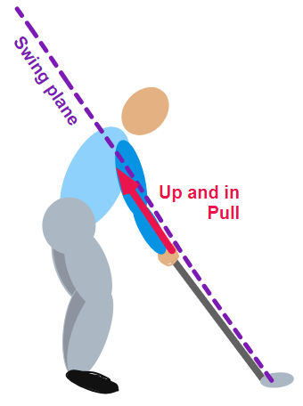 But how can that be? Up and in
is 2-dimensional. It's up and
it's in.
Well, remember that "up" and "in" are concepts -- even primary axes --
in the rectangular "world" coordinate system.
But we are not talking about that system! Remember, that is the fallacy
of thinking the 2D model lives only in a vertical plane -- so it can
handle "up" but it doesn't know anything about "in". And we debunked
that notion already; our 2D model is in the tilted swing plane, not a
vertical plane. It works wherever that plane is for the swing we are
looking at. So -- appropriately enough -- let's look at the swing plane coordinate system.
In that system, we can talk about "up and in" and still stay in the
swing plane. If the "up" and the "in" stay in the same ratio as the
tilt of the swing plane, then "up and in" fits this 2D
model very well. But how can that be? Up and in
is 2-dimensional. It's up and
it's in.
Well, remember that "up" and "in" are concepts -- even primary axes --
in the rectangular "world" coordinate system.
But we are not talking about that system! Remember, that is the fallacy
of thinking the 2D model lives only in a vertical plane -- so it can
handle "up" but it doesn't know anything about "in". And we debunked
that notion already; our 2D model is in the tilted swing plane, not a
vertical plane. It works wherever that plane is for the swing we are
looking at. So -- appropriately enough -- let's look at the swing plane coordinate system.
In that system, we can talk about "up and in" and still stay in the
swing plane. If the "up" and the "in" stay in the same ratio as the
tilt of the swing plane, then "up and in" fits this 2D
model very well.In fact, any force, torque, or motion that is wholly within (or even parallel to) the swing plane fits the 2D swing plane model. It is only things that happen outside those two dimensions that would require a 3D model to handle them. |
||||||||||||||||
An up and in pull may indeed be
a force in the swing plane, but how could we represent it in a 2D
model? To understand, let's first look at the double pendulum as a 2D
model. Before we go any further, let me remind you that this is not a
frontal view of the golf swing; it is a view perpendicular to the swing plane.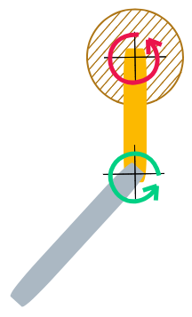 Here
is a simplified diagram of the model. The inner arm of the pendulum
(representing the lead arm of the golfer) is in yellow, and the outer
arm of the pendulum (representing the golf club) is in gray. The two
crossed black lines are pivots. The pivots can be driven by active
motor torques: red for the shoulder torque and green for the hand
couple. Otherwise they are frictionless. The brown shaded area
represents the fixed framework the inner arm is attached to. Here
is a simplified diagram of the model. The inner arm of the pendulum
(representing the lead arm of the golfer) is in yellow, and the outer
arm of the pendulum (representing the golf club) is in gray. The two
crossed black lines are pivots. The pivots can be driven by active
motor torques: red for the shoulder torque and green for the hand
couple. Otherwise they are frictionless. The brown shaded area
represents the fixed framework the inner arm is attached to.The diagram is simplified in that only the active, prescribed torques are shown. Are there other torques at work, and maybe forces as well. Not just yes, but hell yes. If we were doing a proper analysis, we would need to account for:
|
||||||||||||||||
| Now that we understand what the
double pendulum looks like when modeled, let's generalize the model so
it can analyze an up-and-in swing. For that swing the shoulder joint
has to move up and in, in order to pull up and in on the club at the
wrist joint; the power comes from the body (and ultimately the legs);
the hands merely transmit the force to the club. Here are two different ways of modeling the up and in move. 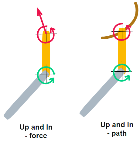 The
first adds an up and in force at the shoulder pivot. We no longer have
a fixed pivot for the shoulder; we have a force, and that force has to
account for the proper movement
of the shoulder pivot itself. Remember all those forces we had to
calculate to analyze the double pendulum? In particular, remember that
there were forces at the shoulder pivot just to keep the pivot pinned
in place? Without the given of the pin, you need to apply those forces
to the pivot first, then add the up
and in force to move the pivot the way you want it to move -- up
and in. All this works, but it is a lot of computation. The
first adds an up and in force at the shoulder pivot. We no longer have
a fixed pivot for the shoulder; we have a force, and that force has to
account for the proper movement
of the shoulder pivot itself. Remember all those forces we had to
calculate to analyze the double pendulum? In particular, remember that
there were forces at the shoulder pivot just to keep the pivot pinned
in place? Without the given of the pin, you need to apply those forces
to the pivot first, then add the up
and in force to move the pivot the way you want it to move -- up
and in. All this works, but it is a lot of computation.The second way to model up and in is more like the double pendulum we started with. We assume a path the shoulder pivot takes (the brown heavy line in the diagram) and a "schedule" of how it moves along the path during the downswing. From that, we can compute the instant-to-instant magnitude and direction of the force needed to move it along the path. If we apply the force we computed from the second method to the first model, we should get theshoulder pivot moving along the same path as the brown line. (That is not a constant force at all; it varies during the downswing. That is also true for the simple double pendulum.) |
||||||||||||||||

 How big is the restoring
torque. Very simple calculation: the force times the moment arm. That is
How big is the restoring
torque. Very simple calculation: the force times the moment arm. That isLast
modified -- Sept 28, 2024
|
|