When it comes to kinetics -- relating torque to motion -- Newton's same
three laws exist. Torques substitute for forces, and we will see other
rotational units substitute for the linear units we have seen earlier.
By the way, "rotational" and "angular" usually mean the same thing when
we talk about dynamics.
Newton's
first law of angular motion:A
body in rotation stays in rotation at the same speed and direction
(same angular velocity) unless acted upon by some torque outside the
object itself.
Exactly the same as for linear motion, except now we are talking about
rotation around an axis.
Newton's
second law of angular motion:If
a torque is applied to a body, the body accelerates according to the
relationship Τ=Iα
Similar to linear motion, except:
Obviously, we substitute torque for force.
Instead of mass, we have I, moment of
inertia, the measure of rotational resistance to motion. Clubmakers to
talk about "MOI", but physicists and engineers have called it I for centuries.
We will discuss more below about what moment of inertia is.
Instead of simple acceleration, we have α, angular
acceleration.
Newton's
third law of angular motion: For every
torque applied by one body to another, there is an equal and opposite
reaction torque.
When you exert a torque on something, it exerts an equal and
opposite torque back on you. We have seen how this works for forces, and it works the
same for torque. Here's a similar pair of videos for torque.
In this video, I am waving a pair of weights left and right with my
upper body at arm's length. The upper body is rotating
back and forth to make it happen. That implies torque. Where is the
torque coming from? The oblique muscles in the middle of the body are
applying the torque, coming from a stationary lower body. The hips are
providing a stable linkage from the obliques to the upper body.
Continuing down the chain, the legs are applying force to the ground in
order to keep the hips in place as they torque the upper body back and
forth. And of course the ground ain't goin' nowhere.
But look what happens when
the lower body is not held in place. I'll answer that question by
sitting on a swivel stool while I wave the same pair of weights. If the
lower body is not actively held stationary (as it was above), then it
will twist back and forth, exactly opposite to the upper body. That is
the equal and opposite torque in action! As the obliques drive the
upper body from below, they also drive the lower body from above. Equal
and opposite! And I can't accurately control what my arms are doing
with the weights because my lower body is twisting back and forth
without any ground reaction forces to stabilize it.
This
hints at what will happen if you try to swing a golf club without any
ground reaction forces. But there are videos around that show it pretty
graphically.
Here's a video of a golfer trying to hit a ball standing
on a frozen lake. Note how the feet spin in the opposite direction
from the golf swing. Not a pretty picture.
There is also a rather well known video of golf coach,
biomechanist, and TV commentator Chris
Como
diving into a pool from a high platform while trying to swing a golf
club. (The video was created by my friend Russ Ryden.).It shows how the
unsupported lower body twists in the opposite direction from the golf
club and the upper body.
Rotation and angular units
Rotation is a change of angle
over time, so we should expect rotational
velocity and acceleration to use units we associate with angles. We are
all familiar with measuring angles in degrees.
There are 360° (three hundred sixty degrees) in a circle, and 90° (a
quarter of that) in a right angle (a quadrant of a circle).
But there are other not uncommon ways of expressing the size of an
angle.
The most familiar one for most of us is the revolution.
You may not think of this as a measure of angle, but it is. One
revolution is 360°, and we usually use revolutions when describing
angular velocity. That unit is RPM, or revolutions per minute. But if
we can use it for velocity, we can also use it for position or
acceleration.
There is a unit of rotation called the radian.
It is derived from trigonometry, and its size is such that 2π radians
is a complete circle, same as 360°. When you do the math, one radian is
approximately equal to 57.3 degrees.
There are others that do not concern us in golf, so I won't
discuss them further. For instance, the military describes angles in
"mils", because that makes arithmetic easier when aiming artillery.
Newton's laws of angular motion, and other formulae derived from them,
require angles to be measured in radians in order to work. (At least if
you are not going to use unit conversion factors, which tends to be
tricky if you don't understand what you are doing.)
So now we know how to express an angle -- a rotational position.
Rotational kinematics and kinetics also requires expressing angular vlocity (position change
per unit time) and angular
acceleration (angular velocity per unit time). Here are some
frequently encountered examples:
Angular
Position
Angular
Velocity
Angular
Acceleration
radians
(This is fundamental for
basic physical formuas
without having to do unit conversion)
Radians
per second
Radians
per second per second
or
Radians per second squared
Degrees
Degrees
per second
Degrees
per second per second
or
Degrees per second squared
Revolutions
RPM
or
Revolutions per minute
RPM
per second
I
sometimes encounter the reaction, "That's just plain silly," if I talk
about, say, a clubface rate of closure of 2400 degrees per second at
impact. "2400 degrees is more than 6 full revolutions. The clubhead
isn't going to do 6 complete revolutions in a swing. That's ridiculous!
Besides, the swing doesn't last a full second."
If that is your reaction, you need to get comfortable with the
notion of an instantaneous rate. That might be 2400 degrees per second
at the moment of impact, but it is much lower than that even ten
milliseconds before impact or after impact. The unit doesn't require the quantity to be the same for a full
second.
In order to get a better feel for it, let's think about a much more
familiar unit: linear velocity in miles per hour (mph). You are driving
on a road with a posted speed limit of 65 miles per hour. You don't
say, "That's ridiculous! I'm not going 65 miles on this trip, and I'm
certainly not holding this speed for an hour." You are comfortable with
MPH as a description of your speed
right now
-- your instantaneous speed -- and you don't feel it has to be
maintained for an hour nor for 65 miles in order to apply.
Now apply
that same reasoning to units like degrees per second. What 2800 degrees
per second means is:
That is the speed it is going "right now", this very instant. If
it kept going at that speed for a full second, then it would indeed
rotate more than 6 full revolutions. But it doesn't have to in order
for its rate right now to be
2800 degrees per second.
Relating angular to linear motion
Just as angular kinetics (force & torque) can be related to linear
kinetics, we can relate angular kinematics (motion) to linear
kinematics.
Remember Τ=Fr? (Torque, force, and radius)
Well
there is a similar relationship for motion: V=ωr. (Linear velocity, angular velocity, and radius)
We have to be careful about the units -- they must be compatible, and
the angular velocity must be in radians per second. From time to time,
we will encounter examples where we have to convert to radians per
second from, for instance, RPM.
Let's
try an example. I am riding my old road bike; it has 27" tires. I am
pedaling at 120rpm, and my 42:14 sprockets (a high gear) gives me a
wheel speed rotation of 360rpm. How fast am I going in miles per hour?
First let's choose an approach to the problem. The bike wheel is spinning about the hub at Xmph.
If the bike is placed -- with its spinning wheel -- on the ground, the
point on the wheel where it touches the ground isn't moving -- but it
is still moving at Xmph with respect to the bike itself. That means the bike itself must be going at Xmph. So all we have to do is find out the speed the wheel is spinning around the hub, and we have the answer. Let's start...
The radius r is 27/2=13.5 inches. (The green measurement is diameter. We need to halve it to get the radius.) That is 1.125 feet.
The angular velocity has to be converted from RPM to
radians per second. My favorite tool for unit conversions like this is
the free Windows application calc98. It tells me that 360rpm is 37.7rad/s.
Now just apply V=ωr.
1.125*37.7 = 42.4 ft/sec = 28.9mph.
That is a sane answer. I know from my bicycle experience that a pedal
cadence of 120 is typical for a road racer on level ground, I am in a
high-speed gear, and road racers go about 25-30mph when they are not
attacking. And by now, you should realize that a lot of these
principles are applicable to other sports as well. It's physics, it
isn't just golf.
Moment of inertia
The "moment of inertia" functions in rotational kinetics
exactly as mass does in linear kinetics. For a given acceleration, you
need either:
more force (linear) or more torque (rotational), or...
less mass (linear) or less moment of inertia (rotational).
Intuitively, it would seem that if you add mass to an object, that
ought to increase its moment of inertia. And that is true. But how much
does it increase it? That depends on the distance from the axis of
rotation. Wait! Does that mean that MOI depends on the axis? If you
choose a different axis, does that change the object's MOI? The answer
is a resounding "yes!"
Before you can talk about the moment of inertia of an object, you have
to specify MOI about which axis. The moment of inertia is calculated
based on how far from the axis each particle of mass is located.
In particular, the MOI is calculated by adding together each tiny chunk
of mass times the square of its distance from the axis. In the diagram,
we have isolated a little chunk of mass m43.
It lies at a distance (a radius) r43
from the axis of rotation. (We are taking the moment of inertia from
that axis.) Mass m43
is so small in size that its size is negligible compared to the radius.
So if each tiny chunk of mass mi is
accounted for, the formula for moment of inertia I is:
I
=
∑
i
(mi
* ri2)
For those readers who are comfortable with
calculus, it isn't hard to
see where that equation goes if you shrink the tiny chunks of mass down
to infinitesimal chunks of size dm.
I = ∫
r2 dm
I show only one integration, but use as many as you need to account for
every particle of mass.
Why r squared?
OK, so each chunk of mass is more important
the farther it is from the axis; that's why r is a factor. But why is the radius squared?
This is one of those questions that you don't actually need to know the answer to, but
moment of inertia might be a little more intuitive to you if you knew
it. The math itself is pretty easy, so hang with it if you can.
Remember that moment of inertia is the measure of a body's resistance
to turning when a torque is applied. It is analogous to mass, the
resistance of a body to moving when a force is applied. Actually, the
linear formulation is more fundamental; we are going to explore how
angular motion is a combination of a coordinated linear motion of a lot
of chunks of mass.
We know that r2
means we multiply by r
twice. It turns out that each time has a different rationale, and let's
look at both. Each comes directly from Newton's second law, F=ma, from linear kinetics.
In the diagram, the gray rod is
rotating through an angle A. I have marked
two particles of mass, one blue and one red. The red one is twice as
far from the axis as the blue one. In order for the object (the gray
rod) to rotate through angle A, the red
particle has to go twice as far as the blue particle. In general, the
distance the particle has to go will be proportional to r, its distance
from the axis.
Let's see how each particle contributes to the total moment of inertia.
We know that T=αI
so clearly
I = T/α
We have just seen on the diagram that linear acceleration a is
proportional to the radius r. In fact, if
we express angular acceleration in radians per second, a=αr so
α = a/r
Plugging this back into our expression above for I:
I
=
T a/r
=
Tr a
So that's the first r.
But that linear acceleration a requires a
force. Where does this force come
from? It has to come from the torque T.
Let's look again at the wrench we originally used to relate force
to torque. But this time, instead of the force producing the torque,
we'll apply a torque at the axis (the crossed centerlines) and see what
forces the torque can produce.
Remember, torque is force times a moment arm, and the moment arm is r. The red
force has twice the moment arm of the blue force. Since torque is
driving things, a shorter moment arm means a bigger force. So the blue
force produced by the driving torque is twice as large as the red force
produced by the same torque. In general, the force is inversely proportional to r. That's a strong hint that we need proportionally more torque for
a given force as r
gets larger. Let's do the math.
Our basic equation for torque is:
T = Fr
Plugging this back into what we found above as an equation for I:
I
=
(Fr)
r a
=
Fr2 a
But we also know -- very basic -- that F=ma. We can
express that as m=F/a.
And we already have an F/a in our
latest expression for I. So:
I
=
F
r2 a
=
F a
r2
= m r2
And there you have it!
Example:
Bicycle wheel
Let's
try a simple example of computing moment of inertia. Here is a
bicycle racing wheel. We want to find its moment of inertia around its
axle, the way it normally rotates in use. There are three major
subassemblies that contribute to I, The rim, the
spokes, and the hub. The moment of inertia of the whole wheel is the
sum of those three components. Let's analyze each in turn.
I have chosen a 700C road touring bike wheel, because data is
relatively easy to come by. I'm using components from an old Gene
Portuesi catalog. Let's look at each component in turn:
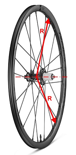
Rim
The rim is a thin ring of mass 400g and a diameter of 700mm. We will do
our computation in grams and centimeters, so that's 70cm diameter or
35cm radius (R
in the diagram).
Suppose we take the "tiny chunk of mass" to be a cross-section through
the rim. Then every chunk has the same R, 35cm. When we
add together all the Rm2
fragments, we get:
Irim = 400g *
35cm * 35cm = 490,000 g cm2
Spokes
A typical bike will have 36 spokes, each of roughly 6 grams mass. We
will make the approximation that they are the length of the radius,
35cm. To compute the I of a spoke, we
will cheat a little; instead of doing the calculus here, we'll go to one of the many engineering reference tables.
(BTW, this table shows the formula we just used for the rim as well; it
is decribed as "thin ring or hollow cylinder".) We are interested in
the "thin rod about end"; the spoke ends at the axis in our simplifying
approximation. (It is not hard to make a more realistic approximation,
but requires physics we are not going to cover -- and it won't matter
all that much.) We will compute the I of a single spoke and multiply it
by 36, the number of spokes.)
Hub
Let's appoximate the hub, obviously contrary to fact, as a simple
hollow cylinder with an outside diameter (OD) of 3cm and an inside
diameter (ID) of 1cm; that would be radii of 0.5 and 1.5. The formula
for a hollow cylinder is in another engineering table. The mass of such a hub
is usually something like 300g.
Total
So the total moment of inertia of the bicycle wheel is
490,000+88,200+375=578,575gcm2
There are some lessons to be learned from this exercise:
There are engineering tables available in textbooks and on
the web that give simple formulas for the moment of inertia of
geometric shapes.
If we can break an object down to an assembly of simple
shapes, we can use the formulas to compute the moment of inertia for
each piece. We have to be careful we are using the formula for the axis
we want. If we get that right, then just add the MOI for each piece to
get the MOI of the entire object.
Mass close to the axis has a lot less effect on the total
MOI than mass further from the axis (larger R). We can see
this very dramatically when we look at the contribution of the hub. It
contains almost a third of the mass (300g out of just over 900g), but
contributes less than 0.1% to the moment of inertia.That is because its
mass averages roughly 1cm from the axis while the rim's mass averages
35cm. That is a factor of about 35, which is greatly amplified because
the distances are squared. 35 squared is over 1200, so each gram of
mass in the hub contributes only 1/1200 of what a gram of mass in the
rim does. This is an important
lesson!
Demonstration
Let's reinforce that last lesson with a demonstration.
Here's a pair of videos of two hanging assemblies with the same mass
but different moments of inertia. The axis we are talking about is the
vertical axis through the center of mass of the assembly. We will nudge
each one with a finger, trying to spin it around that axis and see what
happens. (I made a casual attempt to use the same impulse with my
finger on both assemblies, but I don't think I was very good at it. And
I don't think it would be easy to be good at it, without creating a
mechanism to start the spin.)
The two assemblies are exactly the same -- same PVC tube, same light
gauge nylon line, and same two weight plates -- except for the position
of the weight plates. The one on the left has the plates together
touching the spin axis; the one on the right has the plates as far
apart, and as far from the spin axis, as possible. From what we saw in
doing the calculations above, the one with the weight far from the axis
should have the higher moment of inertia.
And
it does! Look how much slower the assembly on the right spins
back and forth. The torque trying to make them spin is the same, but
the angular acceleration is much lower because the I is much higher
on the right. If you look closely, you can see that the maximum
deflection for the first cycle is larger on the left; that would be due
to the lower I,
but it is also dependent on the impulse from the finger and I was not
too careful to control that. The very different length of the cycle is
a much better demonstration of the difference in moment of inertia.
Last
modified -- Oct 10, 2024
Copyright Dave Tutelman
2026 -- All rights reserved


 Rotation is a change of angle
over time, so we should expect rotational
velocity and acceleration to use units we associate with angles. We are
all familiar with measuring angles in degrees.
There are 360° (three hundred sixty degrees) in a circle, and 90° (a
quarter of that) in a right angle (a quadrant of a circle).
Rotation is a change of angle
over time, so we should expect rotational
velocity and acceleration to use units we associate with angles. We are
all familiar with measuring angles in degrees.
There are 360° (three hundred sixty degrees) in a circle, and 90° (a
quarter of that) in a right angle (a quadrant of a circle).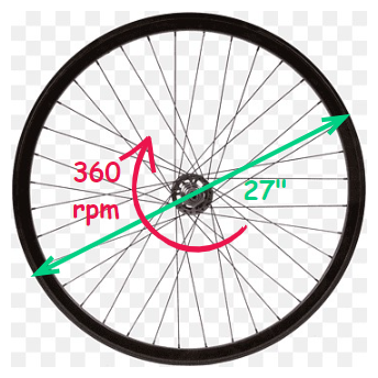 Let's
try an example. I am riding my old road bike; it has 27" tires. I am
pedaling at 120rpm, and my 42:14 sprockets (a high gear) gives me a
wheel speed rotation of 360rpm. How fast am I going in miles per hour?
Let's
try an example. I am riding my old road bike; it has 27" tires. I am
pedaling at 120rpm, and my 42:14 sprockets (a high gear) gives me a
wheel speed rotation of 360rpm. How fast am I going in miles per hour?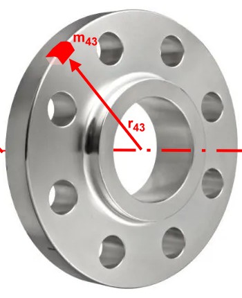
 In the diagram, the gray rod is
rotating through an angle
In the diagram, the gray rod is
rotating through an angle  But that linear acceleration