The
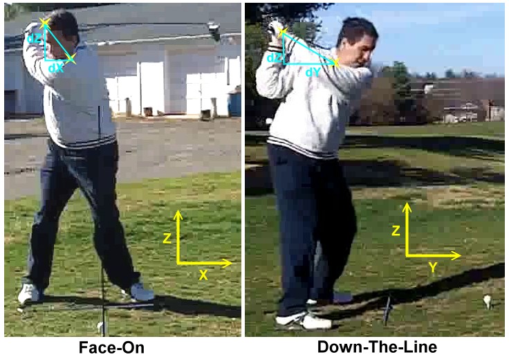
figure is based on the notion that the hands are moving along a curved
path driven by shoulder torque. It is assumed that the shoulder torque
is transmitted to the hands through a lever arm, whose length is the
radius from the hands to the center of rotation.
The
figure is based on the notion that the hands are moving along a curved
path driven by shoulder torque. It is assumed that the shoulder torque
is transmitted to the hands through a lever arm, whose length is the
radius from the hands to the center of rotation.This is a useful model of both the conventional swing and the Leecommotion swing.
- In the conventional swing, the radius is a constant equal to the length of the left arm.
- In the Leecommotion swing, the left arm defines the "track" along which the hands move, but the right arm transmits the torque from the shoulders. The folded right arm is a shorter lever arm, so the force on the hands is greater.
Because r(t) varies, the moment of inertia of the arms, hands, and club (as a unit) also varies. So our model wants to:
- Start with the reality of a varying moment of inertia exposed to the actual shoulder torque created by the golfer.
- Derive a time-varying shoulder torque T(t) that gives the same acceleration to the hands as #1 would, but assuming the moment of inertia were constant.
Let us proceed to derive T(t). The green boxes are the detailed math. If you don't want to follow it in that much detail, you can safely skip them. The important results will be summarized.
Non-Circular Model: Upper Bound
This note in green tells you how to calculate the torque profile for a given non-circular swing. It depends only on high school math and college freshman physics. But if you're not comfortable with algebra and never expect to run the computational model yourself, you won't miss anything if you skip the note entirely.Let's start with notation:
- To = The actual shoulder torque that the golfer is capable of exerting for a golf swing.
- T(t) = The torque profile used as input to the model, as it varies over time.
- Ro = The circular radius in the latter (release) portion of the swing. If the swing is not circular at this point, the model is inaccurate.
- r(t) = The distance from the path to the center of rotation, as it varies over time. Obviously, it becomes Ro late in the downswing.
- Io = The moment of inertia of the arms, hands, and club when fully extended and still with the initial wrist cock. Basically, the moment of inertia as it would have been for the early phases of a normal, circular-path downswing.
- I(t) = The moment of inertia of the arms, hands, and club, when folded to the lever arm of r(t), also as a function of time.
- α(t) = Angular acceleration of the arms, hands, and club, as a function of time.
- M = The mass of the arms, hands, and club.
- K = An arbitrary constant used in computing the moment of inertia. Its value depends on the shape of the body. For most shapes, the formula takes the form I=KMr2 as a quick visit to any table of moments of inertia will attest. Luckily for us, we don't need to compute its value, because it will cancel out of our calculations.
We depend heavily on the elementary piece of physics, T=Iα, the rotational analogy of F=Ma. But we will see it in the form:
| α = | T I |
(1) |
First of all, the angular acceleration over time will be given by the equation (1), where the torque is what the body produces To and the moment of inertia is the actual moment of inertia due to the changed lever arm I(t). In other words:
| α(t) = | To
I(t) |
(2a) |
Our goal is to compute a new torque function T(t) that, when applied to the simple circular double pendulum model, gives the same angular acceleration over time. So:
| α(t) = | T(t)
Io |
(2b) |
Since we are constraining both cases to the same acceleration profile α(t), we can equate (2a) and (2b) to get:
| α(t) = | To
I(t) |
= | T(t)
Io |
| T(t) = To | Io I(t) |
(3) |
Now we need to see how the moment of inertia varies during the early part of the downswing. The only thing that is varying, fortunately, is the radius from the center of the torque to the hands. If the club were flying out from the center, releasing the wrist cock angle, we would have major complications here. But, since it is not, we can compute the moment of inertia to a reasonable approximation by the simple, well-known:
I
= K M r2
Plugging this into the moments of inertia in equation (3):
| T(t) = To | K M Ro2 K M r2(t) |
| T(t) = To | Ro2 r2(t) |
(4) |
Equation (4) is our answer, and it is really simple. The details of the mass and shape of the arms, hands, and club have canceled out; we don't have to worry about them. The formula may not be trivial to use, because we have to find r(t) for the actual swing. That may require a frame by frame analysis of video of the swing. But at least we know what we need from the video, and how to use it when we have it.
As a "sanity test" of equation (4), we would expect T(t) to revert to To in the latter phases of the downswing. And it will, as long as r(t) reaches Ro before the wrist cock angle releases much. And, if you remember, that was one of the constraints we knew up front we would need to impose on the model.
So equation (4) is the way to find T(t) from r(t), and it is remarkably simple. Simply scale T(t) to the inverse square of r(t).
Think about what happens when a spinning figure skater extends or pulls in her arms. With the arms extended, the spin slows down. With the arms tucked in close to the body, the spin speeds up. That is because angular momentum must be constant. That is:
ω1I1
= ω2I2
Where ω is the angular velocity of the skater, and the subscripts 1 and 2 represent extended and tucked arms respectively.
That is very analogous to the case we have here. We have based the analysis on angular acceleration. But bear in mind that acceleration accumulated over time is velocity. And some of that velocity does not remain accumulated as r(t) increases and thus raises the moment of inertia. As the arms extend, conservation of angular momentum demands that we shed some of the angular velocity that previous acceleration had given us.
That is why I labeled this model "Upper Bound". It is a too-optimistic estimate for clubhead speed.
I tried to quantify how optimistic it would be. The math turns out to be messy. Not as much work as a complete rewrite of the simulation, but a major step in that direction. It would have to account for the actual moment of inertia and actual angular velocity, which our formula has so far managed to make cancel out. By explicitly including them, we bring in other complications.
So let us take a slightly different approach -- and a much easier one. We know the model we already have will overestimate our clubhead speed, because we didn't allow for the slowing effect of angular momentum. So let's see if we can come up with another model that will underestimate the clubhead speed. Then we will have a lower bound to go with our upper bound. We won't know clubhead speed exactly, but we will have a range that it has to lie within.
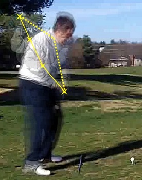
 The model
we will
use is shown in the diagram. Instead of spinning a moment of inertia,
we'll accelerate a point mass. So we will assume all the mass of the
arms and hands to be traveling along the curved track along with the
hands. This means that the shoulder torque will have to accelerate the
mass of the
biceps as much as it accelerates the wrists. This clearly does not give
as much
clubhead speed as we would get from the real swing, because
rotation does not require as much acceleration of mass that is closer
to the center of rotation... But we are treating it as if it did.
The model
we will
use is shown in the diagram. Instead of spinning a moment of inertia,
we'll accelerate a point mass. So we will assume all the mass of the
arms and hands to be traveling along the curved track along with the
hands. This means that the shoulder torque will have to accelerate the
mass of the
biceps as much as it accelerates the wrists. This clearly does not give
as much
clubhead speed as we would get from the real swing, because
rotation does not require as much acceleration of mass that is closer
to the center of rotation... But we are treating it as if it did.The things to notice about this diagram are:
- The black dashed line is the actual path of the hands. The important thing to notice here is that it is not a circle around the shoulder pivot; if it were, then it would be perpendicular to the dotted-line radius. So there is some angle between the actual path and an ideal circular path.
- Shoulder torque produces a force perpendicular to r. That is what torque does. The force is shown in blue, and is of a magnitude equal to the torque divided by r.
- The force can be resolved into components, shown in aqua. One component (the bold one labeled Fa) is tangent to the path of the hands, and so accelerates the hands along their path. The other (the very pale one) does nothing to aid or hinder the progress of the hands, and is rather small as well; it serves to curve the path. But the left arm pull does that, and allows for forces like this, so we can ignore it for most analysis purposes.
Non-Circular Model: Lower Bound
Again, the derivation depends only on high school math and college
freshman physics. And again, you won't miss much
if you skip the note entirely.The notation is similar, but includes linear instead of angular motion:
- To = The actual shoulder torque that the golfer is capable of exerting for a normal, circular swing.
- T(t) = The torque profile used as input to the model, as it varies over time.
- Ro = The circular radius in the latter (release) portion of the swing. If the swing is not circular at this point, the model is inaccurate.
- r(t) = the distance from the path to the center of rotation, as it varies over time. Obviously, it becomes Ro late in the downswing.
- θ(t) = the angle between the actual path and the ideal circular path, also as a function of time.
- F = the force produced by shoulder torque at radius r(t).
- Fa = the accelerating component of F, tangent to the path of the hands.
We know from the diagram above that
F =
To
/ r(t)
(5)
Also from the diagram, we can resolve F into components to get
Fa
= F cos θ(t)
= To cos θ(t) /
r(t)
(6a)
In order to obtain the same velocities along the curved "track", we need to apply the same Fa when we use the standard double pendulum model. So our torque T(t) for the standard double pendulum has to satisfy
Fa
= T(t) / Ro
(6b)
So we have two equations for Fa, (6a) for the curved track and (6b) for the standard double pendulum. Since Fa has to be the same for both, let's set them equal.
| Fa = | To cos θ(t) r(t) |
= | T(t) Ro |
| T(t) = | To | Ro r(t) |
cos θ(t) | (7) |
This is pretty simple, and applying it is similar to applying the upper bound. But wait, it usually gets even simpler.
Remember that the angle θ is not supposed to get too big. Well, if it stays small enough (say, under 10º) we can safely ignore the factor cos θ(t). At 8º the error from ignoring the cosine is only 1%, and is still under 2% at 11º. That sort of error is smaller than most sources of measurement error when it comes to modeling a golf swing. If we assume θ is rather acute and drop out the cosine, we are left with
| T(t) ≈ | To | Ro r(t) |
(8) |
Very simple and manageable!
| Tupper(t) = To | Ro2 r2(t) |
equation (4) |
| Tlower(t) = | To | Ro r(t) |
cos θ(t) ≈ To | Ro r(t) |
equation (8) |
Rewritten as an inequality to reflect the bounding nature of the model:
| To | Ro r(t) |
< T(t) < To | Ro2 r2(t) |
equation (9) |
 This turned out to
be
considerable work. I had a lot of pretty good
video footage of Rock's swing, and my intent was to find frames at the
appropriate moments and measure
This turned out to
be
considerable work. I had a lot of pretty good
video footage of Rock's swing, and my intent was to find frames at the
appropriate moments and measure